
BLOG
Knowledge
Technology and Services
Deformation control in industrial oil tank manufacturing | LILAMA 10
2026-06-26
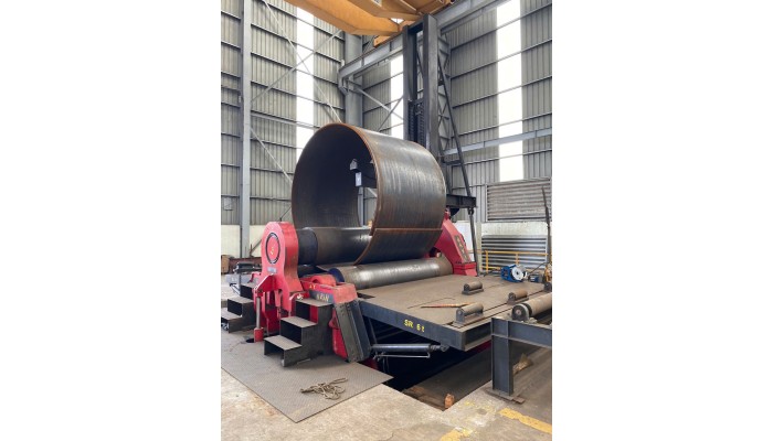
What is deformation control in industrial oil tank manufacturing?
In industrial oil tank manufacturing, deformation control is the process of managing the shape, dimensions, and stability of the tank throughout production stages such as steel plate cutting, plate rolling, assembly, welding, inspection, and finishing. The goal is to ensure that the manufactured tank meets the specified diameter, height, roundness, bottom flatness, shell straightness, and tightness according to technical requirements.
For large-scale oil tanks, deformation not only affects the product's appearance but can also directly impact installability, tightness, weld strength, and operational safety. Therefore, deformation control is one of the most critical factors in industrial tank manufacturing, especially when using thick steel plates and large welded structures.
Why are industrial oil tanks prone to deformation during manufacturing?
Industrial oil tanks are typically fabricated from large, thick steel plates with numerous long welds. During the manufacturing process, steel is subjected to heat, mechanical forces, and its own weight, leading to a risk of deformation.
Key causes of deformation include:
Heat generated during steel plate cutting
Forces applied during plate rolling
Springback after rolling
Misalignment during steel plate assembly
Shrinkage due to welding
Inappropriate welding sequence
Insufficiently rigid jigs or fixtures
Improper lifting, turning, or transportation methods
Untimely dimensional inspection between stages
Among these, welding deformation is one of the most common issues. During welding, the weld zone is locally heated and then cools, creating uneven shrinkage. If not properly controlled, the tank shell can become out-of-round, warped, misaligned at the edges, or experience overall dimensional deviations.
Common types of deformation in oil tank manufacturing
In tank oil manufacturing, deformation can occur at various locations. Below are the common types:
| Type of Deformation | Manifestation | Impact |
|---|---|---|
| Shell out-of-roundness | Uneven shell diameter | Causes difficulties in assembly, welding, and installation |
| Steel plate warping | Plate sags, twists, or is not flat | Affects weld gap and tightness |
| Weld edge misalignment | Two steel edges are not at the same elevation | Reduces weld quality |
| Post-weld shrinkage | Dimensions change after welding | Causes deviations in diameter or height |
| Tank bottom deformation | Bottom is not flat, with convex/concave areas | Affects load-bearing capacity and leak testing |
| Nozzle, manhole deformation | Accessory installation position is misaligned or distorted | Causes difficulties in installing pipes, flanges |
| Overall deformation | Tank is tilted, off-axis, or misshapen | Affects acceptance and operation |
Early identification of deformation types helps businesses implement preventive and corrective measures during the production process, rather than waiting until the product is complete to address them.
Deformation due to steel plate cutting
Steel plate cutting is the first stage that can cause deformation. When using thermal cutting methods such as plasma or oxy-gas, concentrated heat at the cut edge can cause the steel plate to bend, shrink at the edge, or develop localized stresses.
To control deformation during the cutting stage, attention should be paid to:
Develop a reasonable cutting plan according to the drawing
Select a cutting method appropriate for the steel thickness
Control cutting speed and heat input
Allow for machining allowance if necessary
Cut symmetrically or divide the cutting sequence to reduce distortion
Check the straightness, flatness, and dimensions of the blank after cutting
For large-scale oil tanks, small deviations in the cutting stage can accumulate into significant deviations when multiple steel plates are assembled. Therefore, controlling the dimensions of the blank from the outset is crucial.
Deformation during plate rolling
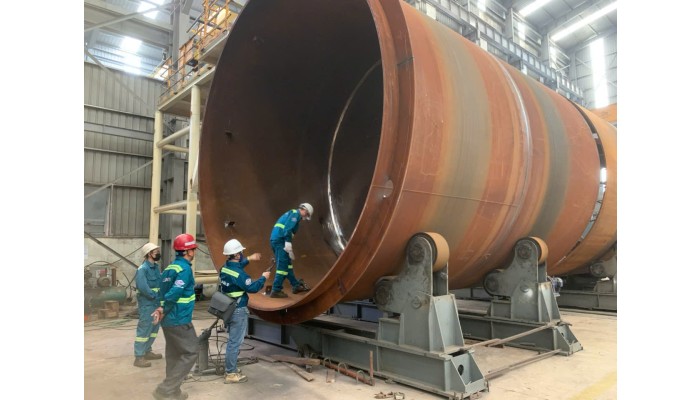
Plate rolling is the stage where flat steel plates are formed into circular arcs or cylindrical shells of the tank. This stage significantly impacts the roundness and overall shape of the oil tank.
Factors affecting deformation during rolling include:
Steel plate thickness
Steel plate width
Rolling diameter
Material yield strength
Rolling machine pressure
Number of rolling passes
Operator experience
Springback phenomenon after rolling
A common issue is that after leaving the rolling machine, the steel plate tends to open up partially due to springback. If not properly calculated and adjusted, the tank shell may not achieve the correct design diameter.
Control measures include:
Check the rolling machine's capacity according to the material, thickness, and required diameter
Trial rolling or adjustment with each pass
Measure the diameter after each rolling step
Use appropriate gauges or measuring equipment
Control the plate ends to avoid excessive straight sections
Re-adjust the rolled arc before moving to the assembly stage
Deformation during tank shell assembly
After rolling, the steel plates are assembled into sections or rings of the tank shell. If the assembly process is not precise, deviations can occur before final welding.
Common issues in assembly include:
Uneven weld gap
Plate edge misalignment
Insufficient roundness of individual sections
Shell sections are not coaxial
Weld position not according to drawing
Insufficiently rigid fixtures, causing movement during welding
To limit deformation, good control is needed over:
Assembly sequence
Tack welding positions
Spacing and rigidity of fixtures
Roundness before welding
Dimensions of each shell section
Weld edge misalignment before final welding
Accurate assembly is a prerequisite for reducing welding deformation. If the product is already misaligned from the assembly stage, welding will exacerbate the deviations.
Welding deformation in industrial tank manufacturing
Welding is the most deformation-prone stage in oil tank manufacturing. During welding, the metal in the weld zone is heated and expands. Upon cooling, this area contracts, creating localized tensile forces. If the shrinkage forces are unbalanced, the structure will deform.
Common types of welding deformation include:
| Type of Welding Deformation | Cause |
|---|---|
| Longitudinal shrinkage | Long welds, high heat input |
| Transverse shrinkage | Large weld gap, many weld passes |
| Angular distortion | Eccentric or asymmetrical welding |
| Shell out-of-roundness | Unbalanced welding around the circumference |
| Plate warping | Plate thinner than weld length or weak fixturing |
| Post-weld edge misalignment | Weak tack welds, unstable fixtures |
To control welding deformation, an appropriate welding procedure and experienced welders are required. The focus should not only be on completing the weld bead but also on considering the welding sequence, heat input, fixture positions, and dimensional inspection after each stage.
Measures to control deformation during oil tank welding
1. Control of welding sequence
The welding sequence significantly influences the direction of shrinkage and the degree of deformation. For large-scale oil tanks, balanced welding, symmetrical welding, or appropriate segment welding methods should be used.
Some commonly applied principles:
Weld from the center outwards to both sides
Symmetrical welding around the axis
Segmented welding instead of continuous welding over excessively long lengths
Intermittent welding at various locations for more even heat distribution
Avoid concentrating heat for too long in one area
2. Control of heat input
Excessive heat input can increase shrinkage and deformation. However, too low heat input can lead to lack of fusion or unstable weld quality. Therefore, welding parameters must be set appropriately for the material, thickness, and applicable standards.
Factors to control include:
Welding current
Welding voltage
Welding speed
Number of weld passes
Interpass temperature
Preheating temperature if required
3. Use of jigs, braces, and fixing methods
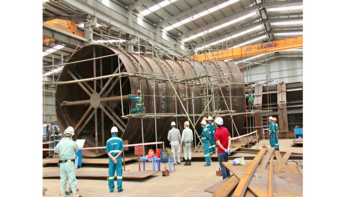
For large-diameter tanks, jigs and braces help maintain shape stability during welding. Without appropriate fixing methods, the tank shell can become out-of-round or shift after welding.
Commonly used measures include:
Using internal braces within the tank shell
Using temporary stiffening rings
Using external fixtures to maintain roundness
Tack welding with sufficient length and correct placement
Checking the rigidity of fixtures before final welding
4. Dimensional inspection after each stage
Dimensional inspection only after product completion is insufficient. In oil tank manufacturing, inspection is required at each stage to detect deviations early.
Parameters that should be checked include:
Tank shell diameter
Roundness of each section
Straightness along the height
Weld gap
Edge misalignment
Tank bottom flatness
Position of nozzles, manholes, stiffening ribs
Overall tilt or axial misalignment
If deviations are detected early, correction will be easier and less costly than addressing them after the product is complete.
Tank bottom deformation control
The tank bottom is an area subjected to significant loads when the tank is filled with oil or water during testing. If the tank bottom deforms, its tightness and load-bearing capacity can be affected.
Causes of tank bottom deformation typically include:
Uneven foundation/support
Bottom plates not properly fixed
Illogical bottom welding sequence
Welding shrinkage concentrated in one area
Bottom plate too large without appropriate welding sequence division
Control measures include:
Check the assembly surface level before assembly
Arrange bottom plates according to the drawing
Tack weld before final welding
Symmetrical or segmented welding
Check flatness after each stage
Avoid concentrating heat for too long in one position
Deformation control at nozzles and manholes
Nozzles, manholes, flanges, and auxiliary components are locations prone to localized deformation. This is because these components are typically welded to the tank shell, creating areas of concentrated heat and stress.
If not properly controlled, errors such as:
Eccentric nozzles
Non-perpendicular flanges
Distorted manholes
Concave or convex areas on the tank shell around the nozzle
Difficulty in installing connecting pipelines later
Control measures include:
Precise machining of openings
Using positioning jigs when installing nozzles
Secure tack welding before final welding
Symmetrical welding around the nozzle
Checking perpendicularity and position after welding
Using reinforcement if required by design
Relationship between deformation control and tightness testing
Deformation and tightness of oil tanks are closely related. When the tank shell is distorted, the bottom is not flat, or welds are excessively shrunk, the risk of leakage at welds and connection points increases.
A quality oil tank not only requires good welds but also must ensure:
Correct design shape
Roundness within permissible limits
Required bottom flatness
Welds free from serious defects
No leakage during tightness testing
No abnormal deformation during hydrostatic or pressure testing
Therefore, deformation control must be carried out in parallel with non-destructive testing, dimensional inspection, and tightness testing.
Why choose an experienced unit for large-scale industrial oil tank manufacturing?
Industrial oil tank manufacturing is not merely a process of cutting, rolling, and welding steel. It is a comprehensive engineering process requiring experience in design, thick steel plate fabrication, large structure welding, deformation control, quality inspection, and on-site installation.
An experienced unit will help customers:
Reduce the risk of dimensional deviations
Minimize post-weld repairs
Ensure manufacturing schedule
Effectively control weld quality
Meet inspection and acceptance requirements
Reduce the risk of leakage during operation
Optimize production and maintenance costs
Especially for oil & gas, chemical, thermal power, or energy infrastructure projects, oil tanks are often critical items requiring high safety standards and comprehensive quality documentation. Therefore, selecting a manufacturer with proven capabilities is a very important factor.
LILAMA 10's capabilities in industrial tank and structure manufacturing
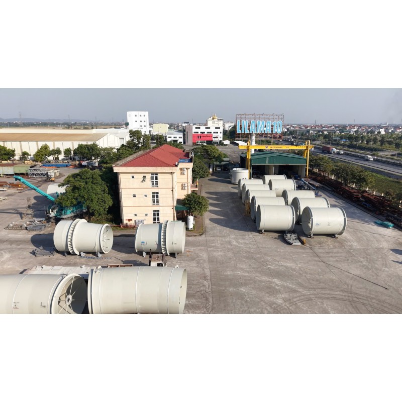
LILAMA 10 is an enterprise with extensive experience in manufacturing, installation, and providing technical services for heavy industrial projects in Vietnam and the region. The company is involved in various sectors such as hydropower, thermal power, oil refining, chemicals, cement, industrial infrastructure, and large-scale steel structure items.
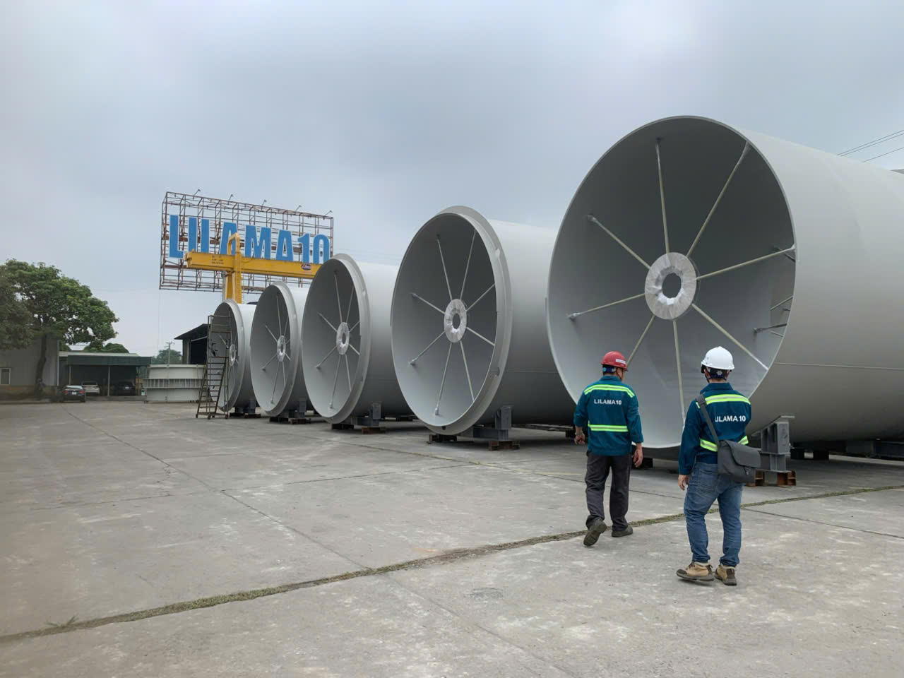
In industrial tank manufacturing, LILAMA 10 benefits from its equipment and steel structure fabrication plant system, a team of engineers, welders, quality control personnel, and on-site construction experience. This is a crucial foundation for controlling high-deformation-risk stages such as steel plate cutting, plate rolling, shell assembly, large structure welding, and post-weld inspection.
In addition to manufacturing capabilities, LILAMA 10 also has experience in installing equipment and structures in large industrial projects. This enables the company to not only focus on in-factory production but also to support customers with on-site assembly, transportation, erection, inspection, and acceptance.
For customers seeking a manufacturer of oil tanks, industrial oil storage tanks, thick steel plate tanks, or large-scale welded structures in Vietnam, LILAMA 10 is a potential choice due to its combined capabilities in manufacturing, welding, quality control, and industrial installation.
Company Information
Construction Installation / Office Rental
LILAMA10 Joint Stock Company is a leading enterprise in manufacturing, installation, and technical services for civil, industrial, transportation, and infrastructure projects.To meet the demands and c ...
PICKUP
Technology & Services
CONTACT
Contact